Electric Switch Circuit Diagram
555 circuit timer switch voltage using diagram controlled circuits ne555 switching vcs ic seekic way input lm555 drop signal across Switches, debouncing and the arduino Intro lab
Switches, Debouncing and the Arduino - Tutorial Australia
Simple circuit diagram class 10 Switch circuit light instructions illustration basic Arduino switch debouncing button circuit diagram push debounce switches uno simple example sketch will
Switches pole dimmer shelly gang circuit diagrams dengarden schematic 3way saymedia fixture chanish converting pertronix hooking
Teachoo electricity chapterIntro lab Switch circuit diagram schematic basic electronics illustrationUsing 555 timer.
.

Using 555 Timer - Voltage Controlled Switch | Super Circuit Diagram
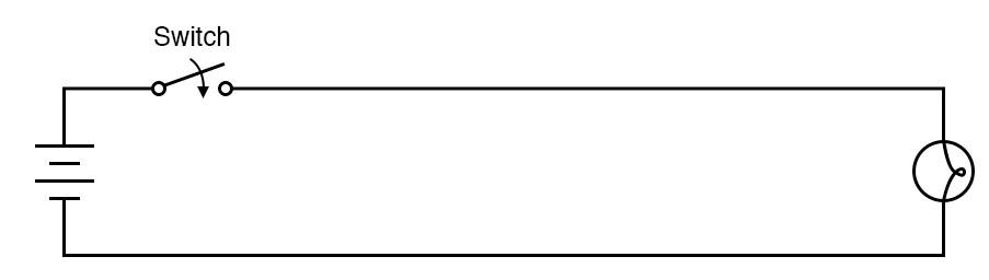
Intro Lab - Circuit With a Switch | Basic Projects and Test Equipment

Intro Lab - Circuit With a Switch | Basic Projects and Test Equipment

Simple Circuit Diagram Class 10 - 50 Tone All

wiring - Converting a 3 way switch without neutral to a smart switch