Emergency Stop Circuit Diagram
Stop start circuit emergency basic interlock testing systems mean do those categories really figure ure fig 2010 An introduction to safety in automation systems Testing emergency stop systems
An Introduction to Safety in Automation Systems
Wiring of the emergency stop lines Note #33: emergency stop system 25 how to wire an emergency stop button diagram
Emergency stop system preliminary cvs actual schematic server
Stop emergency wiring diagram button switch two disconnect estop electrical circuits independent motors kill stackCircuit automation Emergency stop method. emergency stop circuit.Emergency stop circuit.
🔴 emergency stop control wiring of ac/dc drives and plc in process 🔵Emergency stop plc Plc diagrams circuitsWiring button laiser.

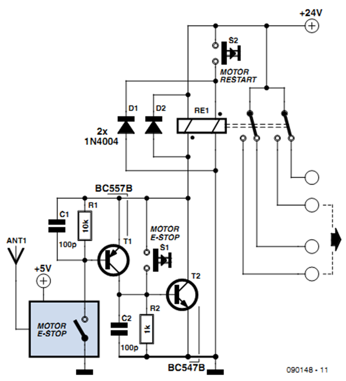
Raj's thoughts.....: wireless and wired emergency stop system
Lines downloadedEmergency stop wired wireless system diagram circuit circuits raj thoughts gr next respectively npn equivalents transistors exist switching many which Stop emergency 24v schematic circuit using input circuitlab created electrical electronicsWiring diagram for an emergency stop button.
Three phase emergency stop wiring diagram .


Note #33: Emergency stop system

🔴 EMERGENCY STOP CONTROL WIRING OF AC/DC DRIVES AND PLC IN PROCESS 🔵

Three Phase Emergency Stop Wiring Diagram - Complete Wiring Schemas

Emergency Stop method. Emergency Stop circuit. - YouTube
Raj's thoughts.....: Wireless and Wired Emergency Stop System

Wiring Diagram For An Emergency Stop Button - THEJOURNALOFPLURALISM

An Introduction to Safety in Automation Systems

batteries - Wiring Emergency Stop button to disconnect two independent

Testing Emergency Stop Systems

embedded - 24v Emergency Stop Input - Electrical Engineering Stack Exchange